|

Please read this article in conjunction with the main article about torque on this site.
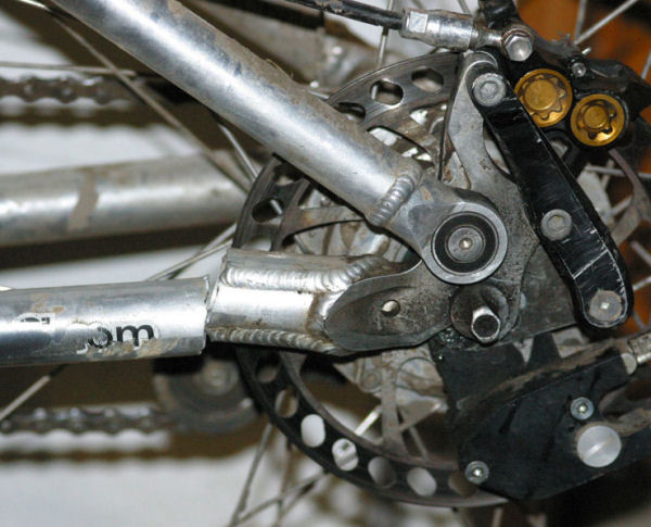
I originally intended to describe torque with internal-gear hubs in my main torque article, but the topic proved so interesting that I decided to give it this separate article.Here's a photo from message #28 on a mountain bikers' forum page, also reproduced on a page of the very informative pardo.net site, which collects reports of bicycle parts failures
The photo shows the left rear dropout area of a bicycle with a Rohloff internal-gear hub and disk brake. Torque from the hub was resolved to the disk brake mount. The bicycle was used for hard off-road riding, with steep climbs and descents. The frame failed after several months of use. The owner had broken two other frames, as shown in other photos he also provided.

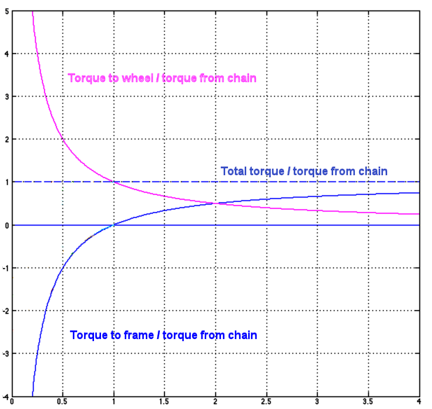
As described in the main torque article, input torque to the rear wheel must equal output torque -- but there's a special twist (literally!) with an internal-gear hub. Not all of the output torque goes to the road. The graph below shows how this works out.
The vertical dimension of the graph represents torque, and the horizontal dimension, the drive ratio. The dashed line represents the total torque output of the hub. We'll assume that the cyclist pedals equally hard, regardless of the drive ratio.
The pink line describes torque at the road -- which is the inverse of the drive ratio. If the hub's drive ratio is 0.5, then the torque at the road is twice that from the chain. If the drive ratio is 1 (unity ratio) the torque at the road equals that from the chain. If the drive ratio is 2, then the torque at the road is half that from the chain-- and so on.

![]()
![]()
Again, input torque must equal output torque -- but with an internal-gear hub, torque to the road does not equal torque from the chain. What happens to the "leftover" torque?
It must be taken up by the bicycle frame. The blue line in the graph represents the torque to the frame.
At a unity drive ratio, all the torque is transferred to the road and there is no torque to the frame -- same as with a drivetrain without internal gears.
At a 2/1 drive ratio, the pink and blue lines cross. The frame torque and road torque each contribute 1/2 of the total output torque. Both torques act in the same direction of rotation: the torque at the road rotates the wheel forward, and the remaining torque tries to rotate the rear triangle of the frame forward.
As the drive ratio becomes even greater, the torque at the road becomes smaller, but the road is still resisting some small part of the torque from the chain. The torque to the frame can, then, never be as great as that from the chain.
At drive ratios lower than unity, on the other hand, the hub multiplies the torque from the chain, and so the torque to the frame, trying to rotate the rear triangle backward, also can become very large. At a drive ratio of 0.5, the torque the the frame is already equal to that from the chain. Where the pink and blue lines go off the graph at a drive ratio of 0.2 (one turn of the wheel for 5 turns of the sprocket), the torque to the road is 5 times that from the chain, and the torque to the frame is 4 times that from the chain.
The lowest ratios of our example hub, the Rohloff Speedhub, is 0.279. The torque at the road in this ratio is 3.58 times the torque from the chain and the torque to the frame is -2.58 times the torque from the chain..
But also the torque at low drive ratios is limited by front-wheel lifting. Let's build on our example from the main article on torque, where the gain ratio -- the ratio of road speed to pedal speed -- is 2. In that example, 100 pounds of drive force at the rear wheel will lift the front wheel, and the cyclist must push down on a pedal with more than 200 pounds of force to lift the wheel.
If the gain ratiois lower than 2, the cyclist must pedal more lightly to avoid lifting the front wheel. The lower the gear, the lower the maximum pedal force.
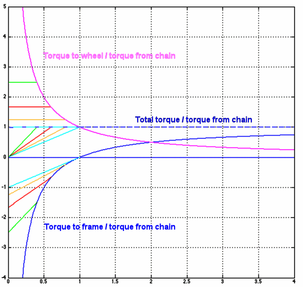
The additional lines in the graph below illustrate this. At the lowest drive ratios, the cyclist can't pedal as hard, and total torque decreases. Torque to the wheel remains constant, but torque to the frame still becomes stronger, the lower the drive ratio. The transition to soft pedaling occurs higher in the hub's range if the bicycle's low gears are achieved mostly by the hub, rather than by the chain drive. Four examples are given:
| Line color | Wheel lifting below | |
|---|---|---|
| green | 0.4 of unity ratio | |
| red | 0.6 of unity ratio | |
| orange | 0.8 of unity ratio | |
| light blue | unity ratio | |

The transition point also depends on the cyclist's strength, the weight and distribution of baggage, slope when climbing, the bicycle's wheelbase, whether the cyclist is bounding up and down while pedaling out of the saddle, etc. On a low recumbent or tandem bicycle, wheel lifting does not occur; on the other hand, it is possible to "pop a wheelie" in a high gear on a conventional bicycle by shifting body mass.
The lowest ratio of a real-world hub known to me is the 0.279 of the Rohloff. Very much lower ratios approaching zero would be impractical due to increasing torque to the frame and because the bicycle would be moving at, literally, a snail's pace.
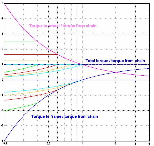
Here's the same graph with a logarithmic horizontal axis, to make gearing ranges directly comparable. Notice for example that the distance from a drive ratio of 0.5 to 1.0 in the graph is the same as that from 1 to 2, and from 2 to 4. The same total range of a hub occupies the same width anywhere across the graph -- and can be raised or lowered as needed by choice of sprockets. Clearly, minimizing the torque to the frame requires that most of the range of a wide-range hub be above unity ratio.

![]()
![]()
The cyclist's high center of mass, and weight transfer to the front wheel, result in rear-wheel skidding, limiting rear-wheel braking of a conventional single-rider bicycle to approximately -0.3 g (relative to the forward direction) -- or less, if the front brake is also applied. Drive force at the rear wheel is limited to approximately 0.5 g by front-wheel lifting.
Braking, and (as we've seen) pedaling in gears above a hub's unity ratio, try to rotate the frame forward along with the wheel; pedaling in gears below unity ratio tries to rotate the frame backward.
Let's install a Rohloff hub on our example bicycle with 0.56 foot long cranks and a 1.11 foot wheel radius. We'll assume the same 200-pound cyclist (with bicycle), and that the cyclist is bearing down on a pedal as hard as possible, with a force of 200 pounds at a radius of 0.56 feet. We choose sprockets for a gain ratio approximately 1.5 to 8.0 -- 20.5 to 108 gear inches, or 1.6 to 8.6 meters development. The chainwheel/sprocket ratio must be 2.75 to achieve this range.
Front-wheel lifting occurs at or below a gain ratio of approximately 2.0 -- when the road speed is twice the pedal speed and the drive force at the road is half of the 200 pounds the cyclist is applying to a pedal. A 2.0 gain ratio is achieved more or less in the Rohloff's 4th gear, with a drive ratio of 0.406. The torque to the road is approximately 101 pound feet, 2.5 times (1 / 0.406) the 41 pound-feet from the chain, and the torque to the frame is approximately 1.5 times the torque from the chain, 61 pound feet. With a wheel radius of 1.11 feet, drive force at the road is 92 pounds, just a bit below what would be required to lift the front wheel. In the lowest drive ratio of 0.279, the torque to the road remains the same, limited by front-wheel lifting, but the torque to the frame is 74 pound feet. The math which gives these results is at the end of this article.
We recall that the maximum acceleration limited by front-wheel lifting is 0.5 g, or 100 pounds in our example, and the maximum deceleration from rear-wheel braking is -0.3 g, or 60 pounds.. The disk brake mount transfers the -60 pound-feet of torque from the brake to the frame - but the 74 pound feet from the hub is greater.
The Rohloff's top gear has a ratio of 1.467, and the cyclist's 200 pound force at the pedal doesn't come anywhere near lifting the front wheel. I'll pass on the math again for now, but torque from the chain to the hub is 41 pound feet, torque at the road is 1 / 1.467, 69%, of this, or 27 pound feet and torque to the frame is the remainder, 14 pound feet. With the disk brake, the maximum is torque is greater, 60 pound feet.
Rohloff specifications rate the highest acceptable input torque as 78 pound feet: 330 pounds of pedal force with 0.56 foot long cranks and 38/16 chainwheel/sprocket. This is more than a solo rider is likely to produce, though it is possible -- as in our example -- to apply a greater force to a pedal than one's weight, by pulling up on the handlebar. Rohloff describes 330 pounds as the highest pedal force which two champion athletes on a tandem can produce. Non-champion athletes who are carrying some extra weight could produce more, though it would be more sensible to gear down..
A higher top drive ratio imposes more forward torque on the frame. The Sturmey-Archer XRF8(W) 8-speed hub's top ratio is 3.24 and so the torque on the frame is 0.69 of that from the chain. With the 38-tooth chainring and 25-tooth sprocket sold with this hub, torque from the chain is 74 pound feet. 69% of this is 51 pound feet, nearly as much as the 60 pound feet which a disk brake can generate with the same rider and bicycle, but taken up at the small radius of the antirotation washer tabs. It is no surprise that antirotation washer failure has been reported with this hub.

In my analysis, I've disregarded impact loadings. These can occur
These loadings can be higher than the ones described earlier, but are harder to quantify. Both could be described as abuse, and would be avoided by a knowledgeable cyclist.
I've also disregarded the small losses due to drivetrain friction. These will lower the torque to the road, and tend to rotate the frame forward, same as the brake.
![]()
![]()
The above graph with the logarithmic axis most clearly illustrates issues raised in this section.
As already stated and as the graphs show, the torque to the frame is lower if the hub mostly gears up rather than down.
On the other hand, greatest efficiency of a hub gear is usally at the unity ratio, with the gears idling -- and this is best as the most often used, level-ground gear, which is much closer to the top of the useful gear range than to the bottom. Lower gears will then impose a large torque on the frame.
With the Rohloff Speedhub, not only is the unity ratio near the top of the range, but also, the other nearby drive ratios use only one or two of the hub's three gearing stages, minimizing power loss. A third gearing stage transposes the upper range of 7 drive ratios downward to provide another 7 lower gears.
A hub may center its range around unity ratio. Typical three-speeds and five-speeds have a single planetary gear system, through which power passes in one direction to raise the drive ratio and in the other to lower it, with a unity ratio in between. Other hubs approximately center the range in more complicated ways: for example, the Shimano 8-speed hub has a unity ratio and three increase gears, as well as an additional gearing stage to transpose them all downward. With any of these hubs, the reverse torque on the frame in the lowest gear will be larger than the forward torque in the top gear -- though not as much as with the Rohloff.
Yet other hubs minimize torque to the frame by avoiding extreme decrease ratios. The Sachs Elan hub had only two gears below unity ratio, and 9 above. Sturmey-Archer 8-speed hubs have only a unity ratio and increase ratios. Efficiency suffers with these hubs in the most-used upper middle part of the gear range.
There are several ways to accommodate large torques from an internal-gear hub, or from a hub brake (disk brake, drum brake, coaster brake, Rollerbrake -- any hub brake).
The center of mass of the bicycle and rider has to be higher than the road surface. There's no way around this! As a result, pedaling transfers weight from the front wheel to the rear wheel. The front end of the bicycle tends to rise and the rear to squat down with each pedal stroke. On an unsuspended bicycle, these effects are small, limited almost entirely to varying compression of the tires. With suspension, pogo-sticking can be disturbing, and can significantly reduce efficiency. Pogo sticking is worse yet if the cyclist is standing on the pedals, so the center of mass moves with respect to the bicycle frame.
The usual solution to the pogo-sticking problem is suspension stiffness which compromises between suspension comfort and pedaling efficiency. Tricky pneumatic valving can make the suspension respond to hard bumps while not bobbing excessively from pedaling. Chain tension, through a linkage, may raise the rear end of the bicycle to counteract pogo sticking, at least if the cyclist is seated. (The slang term is "mechanical advantage" suspension.) This works best at only one rear sprocket size, because the geometry changes somewhat when a rear derailer is shifted to sprockets of other sizes.
With an internal-gear hub, the different torque from the hub in the different drive ratios makes for very different pogo-sticking behavior. Resolving the torque from the hub directly to a suspended part of the frame near the bottom bracket would avoid this problem, but would complicate design and add weight. Compensation might also be achievable with a hydraulic link from the reaction arm to the suspension. With only the single sprocket on an internal-gear hub, compensation could then be optimized in all drive ratios. I don't know of any bicycle which does this.
With any bicycle, compensating rather than only desensitizing a front suspension for pogo sticking would require innovative design -- probably, a hydraulic link between the rear suspension and front suspension. I don't know of any bicycle which does this, either.
![]()
![]()
If you're a math head, you may wish to keep reading and see how the torques described earlier in this article were calculated.
The standard symbol for torque is the lowercase Greek letter tau, τ, and the standard symbol for rate of rotation is the lowercase Greek letter omega, ω.
The torque ratio from chain to road is ωin:ωout, the inverse of the drive ratio. We'll now use ωin:ωout, the torque from the chain, τchain , and the torque at the road τroad, to calculate torque to the frame, τframe.
We know that
τroad = τchainωin:ωout
and
τframe = τchain(1 - τroad)
Substituting,
τframe = τchain(1 - ωin:ωout)
In the case of hubs with very high or very low drive ratios, the torque on the frame can be strong, as shown in the graph and in our examples, above.
Below the transition where hard pedaling would lift the front wheel, the maximum torque to the wheel is constant, but the maximum torque from the chain decreases, and the torque to the frame becomes
τframe = τchain0(1 - ωin:ωout)(ωin:ωout/ωin0:ωout0)
where τchain0 is the torque from the chain at the transition and ωin0:ωout0 is the drive ratio at the transition.
For torque to the frame, the 1 - ωin:ωout term reflects the increasing torque to the frame at lower drive ratios for constant torque from the sprocket (that is, if the cyclist could still pedal; as hard as possible), while the (ωin0:ωout0/ωin:ωout) term reflects the necessary reduction in torque when the drive ratio is so low that hard pedaling would lift the front wheel. The formula reduces to
τframe = τchain0(ωin:ωout - 1)ωout0:ωin0
Note that the last term is reversed, ωout0:ωin0. And, as already mentioned, the transition is not as sharp in reality as is shown in the graphs or formulas.
![]()
![]()
Last Updated: by John Allen