The Geometry of Cantilever Brakes

|

revised by John "Archimedian" Allen
This article is one of several on this site about cantilever brakes. If you are just looking for practical instruction on how to get your cantilever brakes working properly, you might want to start out with my introductory article on Cantilever Adjustment. This article is a bit more of a theoretical examination of the fine points of cantilever brake geometry.
A cantilever, technically, is a structural element supported at one end. A cantilever brake is a rim brake where each brake arm has the brake shoe and the cable attachment both on the same side of the support (the pivot). So that the cable can come from above the tire, the pivot must be below the brake shoe, attached to the frame.
In 1980 and earlier, cantilever brakes were weird, exotic equipment, found mainly on expensive tandems and very high-end touring bikes. They were even rarer than triple chainwheels! Times have changed, and equipment that was once available only to knowledgeable, well-heeled fanatics is now found even on department-store bikes.
Nevertheless, there still remains a bit of mystery to cantilever brakes. The purpose of this article is to clear up this mystery, and to help you do a better job of setting up cantilevers by understanding the nitty-gritty details of the geometry that makes them work.
In particular, it addresses the question of how long to make the transverse cable, or, to put it another way, how low to mount the cable yoke. With most cantilevers, the mechanic has considerable latitude in setting up this cable system, and it makes a real difference in the performance of the brakes, especially with the newer "low-profile" cantilevers.
"Mechanical advantage", or "leverage" is the ratio between how much you get out of a linkage and how much you put in. Mechanical advantage may be looked at as a ratio of forces or as a ratio of distances. Imagine a simple lever with a pivot (fulcrum) 1/3 of the way along it:

Side B will move 2 times as far as side A, but you will have to push on Side A with 2 times the force to lift a weight on Side B.
The crucial point is that changing the leverage (for instance by moving the pivot) will affect both the force and the distance at the same time, since they are two sides of the same coin. You cannot increase the force ratio without reducing the distance ratio.
In the case of bicycle brakes, the mechanical advantage of the system represents the ratio between the amount of force that presses the brake shoes against the rim and the amount of force that the rider's fingers have to apply to the brake levers to create this braking force. If a particular braking system has a mechanical advantage of 8, then squeezing the brake lever with 10 pounds of force will cause the brake shoes to apply 80 pounds of force against the rim. (Actually, somewhat less than 80 pounds would be delivered, due to frictional losses, but for purposes of this article, friction within the brake mechanisms is not important and will be ignored.)
Mechanical advantage can also be viewed as a ratio of distances, rather than forces. A brake with high mechanical advantage will apply a lot of force to the brake shoe for a small amount of finger pressure on the lever; the other side of the coin is that a system with high mechanical advantage will require the hand lever to move a long way to move the brake shoes a short distance toward the rim. If you have too much mechanical advantage, the brake lever will bump up against the handlebar before the brake shoe has moved far enough to engage the rim. If you tighten such a brake up enough to avoid bottoming out the lever, the brake shoes may not retract far enough when the brake is released, and may still drag on the rim.
With caliper brakes, the mechanical advantage is basically fixed by the manufacturer. You cannot change it except by replacing the calipers or the levers or the wheels. (Installing smaller wheels requires you to lower the brake shoes, increasing the effective reach of the calipers, and reducing the mechanical advantage accordingly. For instance, substituting 622 mm (700C) wheels on a bike built for 630 mm (27 inch) wheels will degrade the braking.)
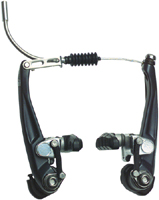
Direct-pull cantilevers, such as Shimano's "V" brakes, also have a fixed mechanical advantage. Since their pivots are below the level of the rim, smaller wheels give more mechanical advantage, rather than less as with caliper brakes. Traditional cantilever brakes, however, allow the mechanic to adjust the mechanical advantage to a considerable extent, mainly by adjusting the length of the transverse cable and the height of the cable yoke.
![]()
![]()
Other brakes with pivots on the fork blades or frame -- U brakes and Roller-cam brakes -- have the brake shoe and the cable attachment are on opposite sides of the pivot. These are not cantiliver brakes, they are a variety of centerpull brakes.
![]()
![]()
Shimano ("Servo-Wave" ®) and Odyssey both make mountain-bike type levers with a variable mechanical advantage that increases as the lever is pulled.
| Yoke Angle (Degrees) |
Mechanical Advantage |
|---|---|
| 90° | 1 |
| 80° | 1.015 |
| 70° | 1.063 |
| 60° | 1.15 |
| 50° | 1.31 |
| 40° | 1.55 |
| 30° | 2 |
| 20° | 2.92 |
| 10° | 5.76 |
| 5° | 11.47 |
| 0° | Infinity! |
A 0 degree yoke angle would represent the shortest possible transverse cable, running in a perfect straight line along the top of the cable yoke.
As you can see from the table, the shorter and straighter the transverse cable, the more difference it makes. This effect is what makes it possible to make a low-profile brake with good stopping power.
![]()
![]()
With low-profile cantilevers,, the shoe needs to be extended inward from the arm, increasing the effective cantilever angle . The unsupported length of shaft connecting the brake shoe to the arm may cause an increased tendency to squeal, but that is one of the inherent trade-offs of low-profile brakes.
Many newer cantilevers replace the separate transverse cable and yoke with "link wire." This is a cable carrier that has a length of narrow housing running from the yoke to the anchor arm. The primary cable runs through this housing, and forms half of the transverse cable. There is a guide line printed on the round yoke, which is intended to be lined up with the exposed side of the transverse cable.
Link wires are commonly available in five lengths:
| Code | Length |  |
|---|---|---|
| S | 63 mm | |
| A | 73 mm | |
| B | 82 mm | |
| C | 106 mm | |
| D | 93 mm |
If you substitute a conventional yoke and separate transverse cable, you may be able to increase the mechanical advantage slightly on a particular bicycle. In general, the stock set up works about as well as possible, but only if you use the Shimano guide.
Since the yoke angle is so critical to the mechanical advantage, the mechanical advantage gets less and less as the brake is engaged, and as the brake shoes wear down. The short transverse cables necessary to get high mechanical advantage from low-profile cantilevers exaggerate this effect, because the yoke angle gets larger for a given amount of upward travel of the yoke. Thus, low-profile cantilevers should be set up with minimum pad clearance if you want to get high mechanical advantage when the brake is actually engaged.
![]()
![]()
The latest thing in cantilevers is the direct-pull cantilever, popularly known by Shimano's trademark "V-Brake". These resemble very tall, low-profile cantilevers, but they do not have a separate transverse cable. They are a side-pull, rather than center-pull design. One arm has the housing stop, and the inner cable runs from the top of that arm to an anchor bolt on the top of the opposite arm. Direct-pull cantilevers have a very high mechanical advantage, which makes them unsuitable for use with conventional levers. If you do use conventional levers with direct-pull cantilevers, the excessive mechanical advantage of this combination will either cause the brake shoes to rub on the rim when they are at rest, or the brake lever will bottom out against the handlebar, depending on the cable adjustment.
Also see my article about direct-pull cantilevers
There are a few new aftermarket gadgets that permit you to use conventional brake levers with direct-pull brakes. These generally use eccentric or doubled pulleys to cause them to pull farther (but less hard) than the incoming cable pulls.
![]()
![]()
There is a direct trade-off between how much force you get and how far the parts travel. Given a mechanical advantage of 8, pulling the brake lever in by 16 millimeters will only move the brake shoes 2 millimeters closer to the rim. The more mechanical advantage you have, the closer the brake shoes will be to the rim at their rest position. This is not a problem with a perfectly true wheel, but can cause the brake shoes to rub too easily on rims that have seen better days.
There is a case to be made for less than maximum mechanical advantage on the front brakes of bikes that are aimed at less experienced riders, lest they lock up the front wheel and hurt themselves.
| With a brake set up for maximum mechanical advantage, the shorter transverse cable has a shallower yoke angle. This may make it difficult or impossible to unhook the transverse cable for wheel removal. For some riders, it may be a worthwhile trade-off to give up some braking power for the sake of easier wheel removal.
On touring bikes with high-mechanical-advantage "æro" brake levers, excessive mechanical advantage may cause the brake to run out of lever travel, so that the lever hits the handlebar. Shimano makes an extra-wide cable yoke for such applications, but you can achieve the same effect by lengthening the transverse cable, unless the bike has such a small frame that you run out of room. |
|
If you reduce flex in the system, you can set the brake for more mechanical advantage without running out of lever travel. I would suggest the following:
The shoes should be set up so that they make good firm contact with the rim. They should be slightly toed in, but not excessively. The vertical angle of the brake shoe should also be adjusted correctly so that it gets the largest possible contact area with the rim.
| Compatibility/Interchangeability of Brakes with Frame-Mounted Pivots | |||
|---|---|---|---|
| Cantilever Type |
Frame Pivot Studs |
Levers | Cable Routing |
| Direct Pull, V-Brake ® |
Below the Rim | Long Pull Low Tension |
Cable comes in from the side. Lower housing stop is part of the cantilever. |
| Traditional Center-Pull Cantilever |
Standard Short Pull High Tension |
Cable runs down the bicycle's center line. Lower rear housing stop on frame, either special braze-on, or mounted to the seatpost bolt. Front housing stop on headset, fork or handlebar stem . |
|
| U-Brake |
Above the Rim | ||
| Roller-Cam | |||
![]()
Last Updated: by John Allen